The Marine Exhaust Boost Engine (MEBRE) concept emerges from a long-standing challenge in internal combustion engine (ICE) engineering: how to extract additional useful work from fuel energy that is otherwise lost as exhaust heat, while simultaneously mitigating emissions and maintaining operational reliability in heavy-duty applications. When examined through a systematic review lens, the proposed architecture does not stand in isolation; rather, it synthesizes multiple established but previously disconnected ideas—exhaust energy recovery, staged expansion, water-assisted combustion, rotary valve breathing, and electrically assisted turbocharging—into a single theoretical framework. This discussion situates the MEBRE concept within the broader body of engine research, critically evaluates its theoretical advantages and limitations, and clarifies its potential relevance to future marine propulsion systems.
3.1 Reframing Efficiency Limits in Marine Internal Combustion Engines
Conventional marine diesel engines remain constrained by fundamental thermodynamic inefficiencies. Even state-of-the-art large-bore diesel engines typically convert only 30–48% of fuel chemical energy into mechanical work, with incremental improvements reaching approximately 50% under optimized conditions (Heywood, 1988; Heywood, 2018). Exhaust gas enthalpy, which can account for more than one-third of total energy losses, represents a persistent inefficiency that turbocharging alone cannot fully recover. As reviewed in prior thermodynamic analyses, single-stage turbochargers are inherently limited by pressure ratios, turbine efficiency, and turbo lag, particularly under transient load conditions common in marine operations (Lee et al., 2019).
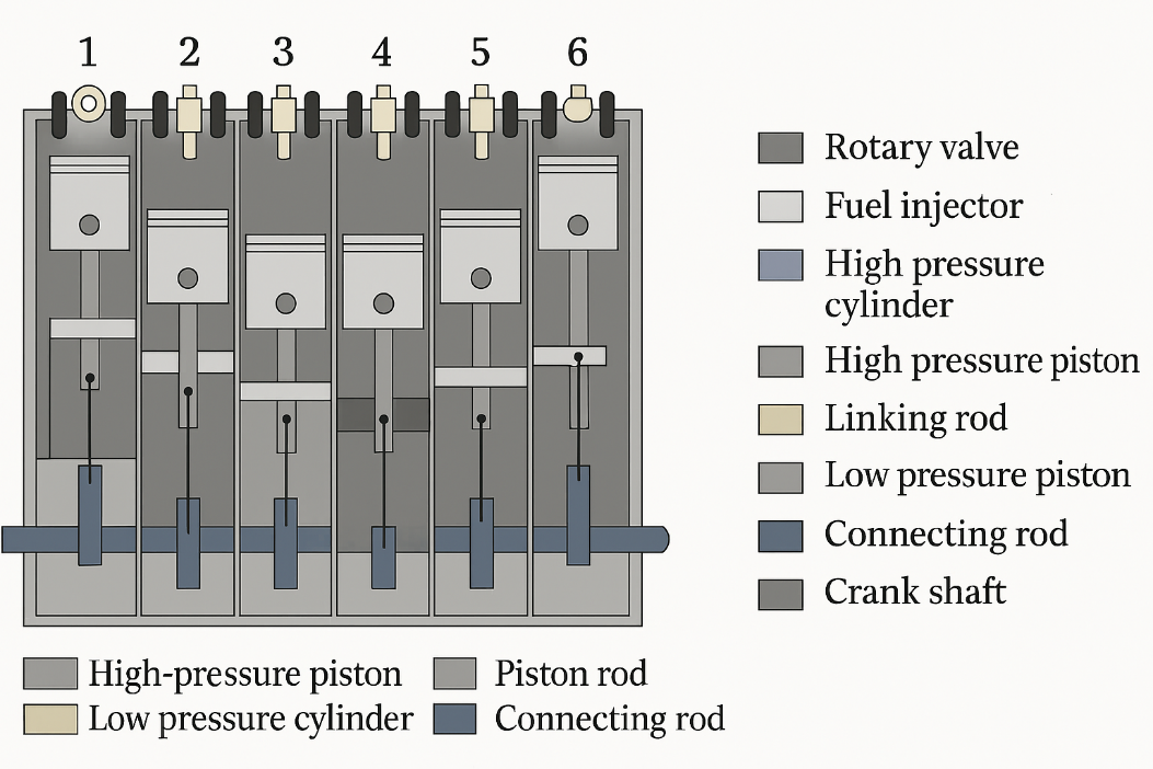
The MEBRE design addresses this limitation by conceptually extending the expansion process beyond the conventional exhaust stroke. By introducing a secondary low-pressure piston group mechanically linked to the primary high-pressure pistons (Figure 1 and Figure 2), the engine attempts to reclaim exhaust energy through a secondary mechanical expansion phase rather than dissipating it entirely through the turbine. This approach conceptually aligns with earlier multi-stage expansion engines, including five-stroke architectures, but adapts them to a marine-scale diesel context where low rotational speed and high torque dominate operational requirements.
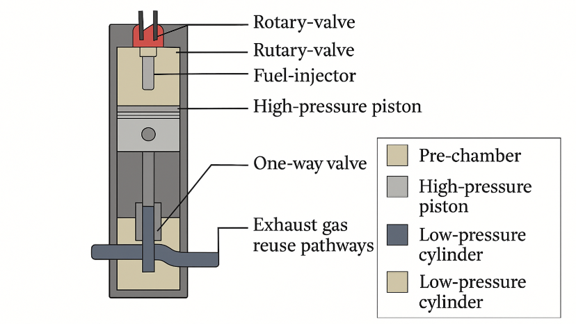
Figure 2. Simplified schematic of the proposed multi-expansion cylinder arrangement showing a high-pressure (HP) combustion cylinder coupled to a low-pressure (LP) expansion cylinder via a one-way exhaust transfer valve. The HP cylinder performs the primary combustion and initial expansion; partially expanded exhaust is routed through the transfer valve into the LP cylinder for a second expansion, improving recovery of exhaust enthalpy. The figure also indicates the exhaust outlet directed toward the turbocharger turbine to preserve boost while enabling staged expansion.
3.2 Exhaust Energy Recycling as a System-Level Strategy
From a system integration perspective, the dual piston-group architecture represents a shift from component-level optimization toward whole-cycle energy management. As illustrated in Table 1, the synchronized firing order allows combustion, exhaust, secondary expansion, and compression assistance to occur concurrently across different cylinders. This rhythmic overlap is not presented as an experimentally verified mechanism, but rather as a theoretically coherent timing strategy designed to smooth torque delivery and reduce crankshaft imbalance.
Table 1. Rhythmic Synchronized Firing and Expansion Cycle of the Marine Exhaust Boost Engine (MEBRE).
Each high-pressure combustion event is deliberately paired with a low-pressure exhaust expansion event, ensuring that exhaust gas energy is utilized twice before final release to the turbocharger.
The linking-rod and shared crankshaft mechanism enable mechanical energy transfer from HP cylinders to LP cylinders without introducing abrupt torque spikes.
The rhythmic sequencing distributes thermal and mechanical loads evenly across the crankshaft, reducing vibration and fatigue.
After the secondary expansion stroke, exhaust gas exits the LP cylinder with sufficient momentum to drive a large turbocharger, even after partial energy extraction.
One LP cylinder is always in a clearing or preparation phase, ensuring uninterrupted cyclic operation (see Figure 2.0).
This rhythmic firing strategy is central to the conceptual validity of the MEBRE architecture. It demonstrates how exhaust energy recovery, crankshaft balance, turbocharger efficiency, and emission mitigation are treated as interdependent system elements, rather than isolated optimizations. The table thus provides a reproducible conceptual framework suitable for future computational modeling and simulation-based validation.
|
Cycle Step
|
High-Pressure Cylinder (Primary Group)
|
Low-Pressure Cylinder (Secondary Group)
|
Functional Description of the Synchronized Event
|
|
1
|
Cylinder 1 – Combustion stroke
|
Cylinder 5 – Expansion stroke
|
Combustion in HP cylinder 1 delivers primary torque while simultaneously driving the LP piston to expand previously used exhaust gas, extracting secondary mechanical work.
|
|
2
|
Cylinder 5 – Combustion stroke
|
Cylinder 3 – Expansion stroke
|
Exhaust gas expanded in LP cylinder 3 is energized by crankshaft coupling from HP cylinder 5, maintaining continuous torque transfer.
|
|
3
|
Cylinder 3 – Combustion stroke
|
Cylinder 6 – Expansion stroke
|
HP combustion sustains LP expansion, ensuring uniform exhaust pressure delivery toward the turbocharger inlet.
|
|
4
|
Cylinder 6 – Combustion stroke
|
Cylinder 2 – Expansion stroke
|
Coupled motion prevents pressure collapse in LP cylinder, minimizing pulsation losses and stabilizing turbocharger drive.
|
|
5
|
Cylinder 2 – Combustion stroke
|
Cylinder 4 – Expansion stroke
|
Exhaust gas receives a second energetic push, enhancing kinetic energy recovery before discharge.
|
|
6
|
Cylinder 4 – Combustion stroke
|
Cylinder 1 – Expansion stroke
|
Completion of rhythmic cycle; LP cylinder 1 is emptied and prepared for the next exhaust recovery phase.
|
The conceptual advantage lies in the coupling of high-pressure combustion work with low-pressure exhaust recovery. Unlike traditional compound engines or bottoming cycles—which often require separate turbines or Rankine loops—the MEBRE approach
integrates exhaust recovery directly into the reciprocating mechanism. In theory, this could reduce parasitic losses associated with auxiliary recovery systems while maintaining mechanical simplicity at the system boundary, even if internal linkages become more complex.
3.3 Rotary Valve Adoption and Engine Breathing Reconsidered
A central pillar of the MEBRE concept is the replacement of conventional poppet valves with a rotary valve system (Figure 3). Decades of engine research have shown that while poppet valves offer excellent sealing, they remain a fundamental bottleneck to airflow, particularly at higher volumetric demands (Watson, 1991). Historical attempts to eliminate this bottleneck—ranging from desmodromic systems to camless actuators—have largely failed to achieve widespread adoption due to complexity, cost, or durability concerns.
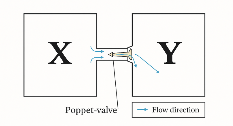
Figure 3. Flow between chambers X and Y controlled by a poppet valve.
Rotary valves, by contrast, offer an intuitively elegant solution: unobstructed flow paths, elimination of valve springs, and reduced valvetrain mass. The discussion of Ralph Watson’s successful long-term rotary valve operation and contemporary developments by Vaztec provides important contextual grounding, demonstrating that sealing challenges, while significant, are not insurmountable. The proposed use of a water–oil mixture as a dynamic sealant
reflects an attempt to leverage onboard marine infrastructure (e.g., oily water separators) rather than introducing entirely new subsystems.
Nevertheless, the discussion must acknowledge that rotary valve sealing remains one of the most critical uncertainties. Thermal expansion, wear, and long-term sealing stability under continuous high-load marine operation remain unresolved without simulation or experimental validation. Thus, within a review framework, the rotary valve is best interpreted as a high-potential but high-risk enabling technology rather than a guaranteed improvement.
3.4 Integration with Advanced Combustion and Pre-Chamber Ignition
To further enhance efficiency and combustion stability, the proposed engine architecture integrates a pre-chamber combustion system inspired by Maserati’s high-performance Nettuno V6 engine. In this design, ignition occurs first within a small pre-chamber, generating high-energy flame jets that propagate rapidly into the main combustion chamber through calibrated orifices. This process ensures faster, more complete combustion, improved lean-burn capability, and reduced emissions. The configuration and operation of the pre-chamber and injector arrangement are illustrated in Figures 4 and 5.
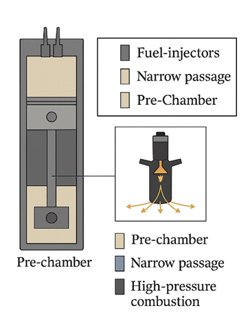
Figure 4. Pre-chamber fuel injection system integrated with high-pressure combustion chamber.

Figure 5. Top view of pre-chamber fuel injection system showing flame jet pathways.
In the present concept, multiple computer-controlled fuel injectors are employed within and around the pre-chamber to precisely meter fuel delivery, particularly under lean operating conditions (Figures 4 and 5). For enhanced reliability in extreme or cold environments, a high-wattage laser ignition system is incorporated as an auxiliary ignition source. Furthermore, the pre-chamber geometry is refined using a shaped-charge–inspired profile to directionally focus combustion energy toward the piston crown, thereby increasing thermal efficiency and power output while minimizing emissions (Figure 4).
3.5 Comparative Assessment and System-Level Advantages
Although rotary valve sealing efficiency may be marginally lower than that of conventional poppet valves, the associated losses are minor when compared to the cumulative inefficiencies introduced by traditional valve trains and their auxiliary systems. Empirical and conceptual comparisons indicate that rotary valve engines can achieve superior overall efficiency, reduced mass, and simplified construction. The reduction in required components, as summarized in Table 2, underscores the economic and operational advantages of the rotary valve system. Collectively, these characteristics support the feasibility of rotary valve technology as a practical, scalable, and high-efficiency alternative for future internal combustion engine applications.
Table 2. Comparison of Components in Poppet Valve Engine vs. Rotary Valve Engine. Comparative components list between the average poppet valve engine and "Vaztec" rotary valve engine.
|
Component
|
Poppet Valve Engine (Qty)
|
Rotary Valve Engine (Qty)
|
|
Intake Valve
|
1
|
–
|
|
Exhaust Valve
|
1
|
–
|
|
Intake Valve Seat
|
1
|
Upper RV Seal (1)
|
|
Exhaust Valve Seat
|
1
|
Lower RV Seal (1)
|
|
Valve Spring
|
2
|
–
|
|
Valve Guide
|
2
|
–
|
|
Valve Seal
|
2
|
Gland Gasket (4)
|
|
Valve Spring Washer
|
2
|
Thrust Washer (2)
|
|
Valve Spring Retainer Clips
|
4
|
–
|
|
Rocker Arm
|
2
|
–
|
|
Adjustment Screw
|
2
|
–
|
|
Rocker Pivot Nut
|
2
|
–
|
|
Locking Clips
|
2
|
–
|
|
Rocker Pivot Stud
|
2
|
–
|
|
Pushrod
|
2
|
–
|
|
Cam Follower
|
2
|
–
|
|
Camshaft
|
1
|
Rotary Valve (1)
|
|
Gears
|
2
|
Sprockets (2)
|
|
–
|
–
|
Support Bearings (2)
|
|
–
|
–
|
Belt (1)
|
|
Total Components
|
33
|
14
|
3.6 Water Injection, Combustion Temperature Control, and NOx Mitigation
One of the more innovative—and controversial—elements of the MEBRE concept is direct distilled water injection into both high- and low-pressure combustion environments (Figure 5). Water injection is not a novel idea; it has been historically applied in aviation engines and high-performance systems to suppress knock and control combustion temperature. However, the MEBRE framework reframes water injection as a primary thermodynamic lever rather than an auxiliary safeguard.
The theoretical basis for this approach is well supported by combustion chemistry. Thermal NOx formation, governed primarily by the Zeldovich mechanism, increases exponentially at combustion temperatures above approximately 1,600°C (Zeldovich, 1946). By absorbing latent heat during phase change, injected water reduces peak flame temperatures while simultaneously generating additional expansion work through steam formation. The discussion appropriately links this mechanism to the possibility of operating at higher air-to-fuel ratios—beyond traditional diesel stoichiometric limits—without exceeding NOx thresholds.
This conceptual trade-off is particularly relevant in marine contexts, where regulatory pressure on NOx and sulfur oxide emissions continues to intensify. However, it must be emphasized that water injection introduces its own challenges, including corrosion risk, injector durability, and control complexity. The reliance on onboard fresh water generation systems partially
mitigates logistical concerns, but long-term impacts on engine materials remain speculative within the current framework.
3.7 Electrically Assisted Turbocharging and Operational Resilience
The integration of a BLDC motor and magnetic freewheel into the turbocharger assembly (Figure 6 and Figure 7) represents a strategic response to turbo lag, fuel quality variability, and emergency operational demands. Electrically assisted turbocharging has been explored in automotive research, but its application in low-speed, high-mass marine engines introduces a distinct operational logic.

Figure 6. Sequential stages of pre-chamber combustion with distilled water spray integration. High energy flame jet moving direction and direct water spray in the live combustion process
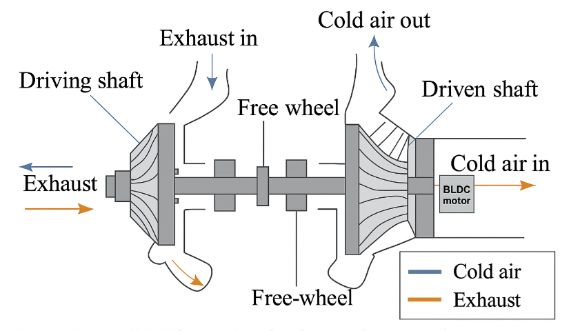
Figure 7. Schematic of exhaust-driven turbo-compressor with BLDC motor assist. Highly complex turbocharger to act as turbocharger and occasionally super charger both
Rather than prioritizing transient acceleration alone, the MEBRE concept frames electric assistance as a reliability and adaptability feature. The ability to operate effectively on low-grade heavy fuel oil, maintain boost during fouling conditions, and deliver rapid power increases during emergencies (e.g., collision avoidance) reflects real-world marine priorities. The magnetic freewheel mechanism, while novel, is conceptually aligned with existing electromechanical coupling strategies used in high-torque industrial systems.
From a review standpoint, this subsystem exemplifies how hybridization in marine engines may evolve differently from road vehicles—prioritizing robustness and fuel flexibility over peak efficiency alone.
3.8 AI-Assisted Control and System Complexity
The proposed AI-based engine management system (Figure 8, Figure 9) reflects a growing trend toward data-driven control in complex mechanical systems. By integrating combustion temperature, exhaust parameters, fuel quality, and environmental conditions into adaptive injection and timing strategies, the MEBRE framework acknowledges that such a complex engine architecture cannot be governed by static control maps alone.

Figure 8. Schematic of ratchet mechanism with integrated permanent and electromagnets. Highly complex turbocharger to act as turbocharger and occasionally super charger both
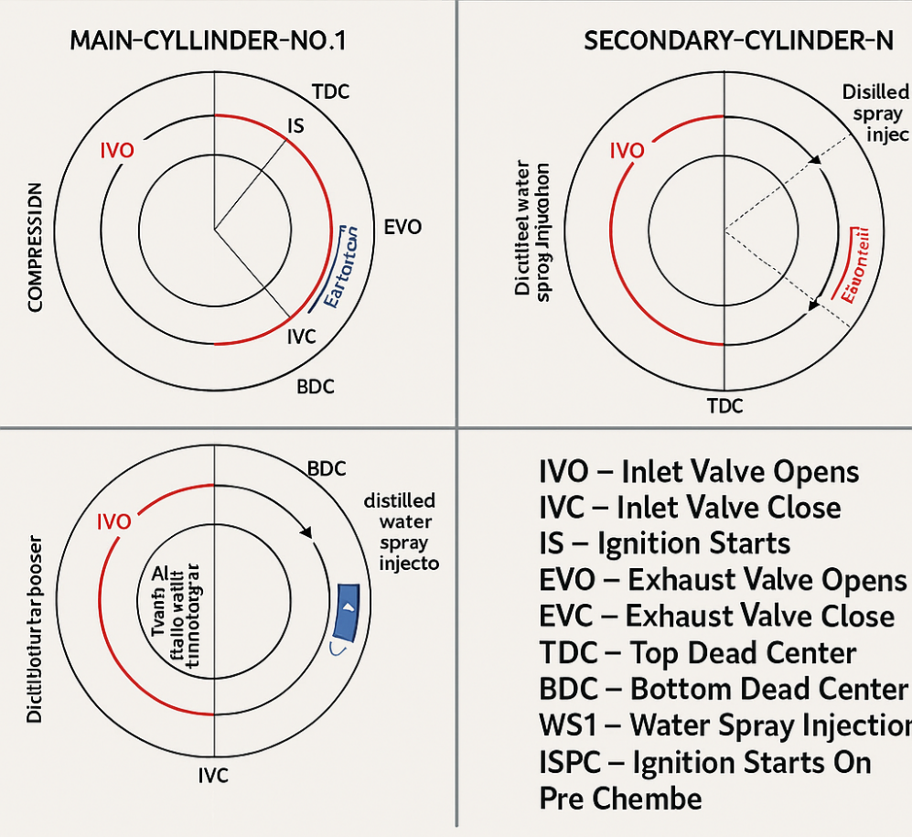
Figure 9. Valve timing and injection phases for main and secondary cylinders with water spray integration. MEBRE engine’s complex synchronized timing diagram
However, this also introduces a critical discussion point: system complexity versus operational reliability. Marine engines are traditionally valued for their predictability and serviceability under harsh conditions. While AI-driven diagnostics and control offer potential gains in efficiency and maintenance forecasting, they also require redundancy, cybersecurity considerations, and crew training—issues that fall beyond thermodynamic performance but are central to real-world adoption.